The Elliot Bros GPO Morse Key from the age of Electromagnetic Telegraphy
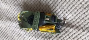
I recently purchased at auction, a lot described as a “ British 1916 Elliott Bros GPO Pattern Morse key mounted on a wooden plinth”. With fees and delivery charges it cost me £33.00
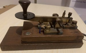
FIGURE 1: Elliot Bros GPO Morse key c 1916
It will need some restoration and a new spring and couple of parts don’t look quite right so it might be a copy, but further research will confirm this, and I will describe that work in a future article. This key is probably the oldest in my collection but I was familiar with the manufacturer and wondered if it was ever used in the age of Electromechanical Sounders. I thought was worth further investigation.
The Elliot Bros company has an interesting history. It had its origins in1850 as a company founded by William Elliot together with his two sons who became began trading as William Elliot and Sons and were based at Century Works in Lewisham, London. In 1854 it became known as Elliot Bros and produced optical, surveying, navigational scientific instruments for home and overseas customers including many famous scientists, then working on the new applications for electricity. including batteries and galvanometers and in 1876 a new works was established in St Martins Lane, London to supply the growing demand for telegraphy equipment together with switchboard components and measuring instruments for the lighting, traction and power industries. Elliot Bros and its successors would continue to grow and develop through innovation, takeovers and amalgamations as a high-tech company, eventually, over time, becoming part of GEC, GEC Marconi and currently BAE Systems Ltd. It was one of the first suppliers of electronic computers and control systems in the 1950’s.
Looking at the morse key with its GPO attribution I started thinking about how quickly telegraphy developed in this country with messages being sent country and world-wide using morse code. Each large town and city would have telegraph offices based in Post Offices and railway stations where the telegraphist would tap out their messages, at so many “old pence per word,” to be received far away instantaneously and delivered by the telegram boy who would often to be told to wait for a reply.
Of course, morse code wasn’t sent then as we know it today. It was all sent over wires connecting one telegraph office to the next. This was all due to the invention of electricity and the battery plus the development of electromagnetism by Michael Faraday in the 1830’s. American academic Professor Samuel Morse and his assistant Alfred Vail were working on electromagnetic devices to record switched voltages on a moving paper tape in the 1840’s. They developed what was to be known as American or Railroad Morse Code.
Although we attribute the code to Morse, it was Vail who invented the system of assigning long and short voltages to different letters in the alphabet to form a “code” of dots and dashes, which could be transcribed on a moving paper tape and read by the recipient on a device known as a Register
American Morse Code uses different time lengths; a dot, a short dash (two units), a long dash (four units for the letter L) and very long dash (five units for the number 0). It also uses gaps within letters meaning a character might consist of a mix of clicks and pauses. International Morse Code which was developed a little later uses uniform dots and dashes.
The basic telegraph system comprises an electrical circuit connected by wires to a voltage source (battery) using a morse key as a switch to energise a relay in the Register. Applying the voltage to the relay coil induces an electromagnetic field which causes the iron core to move in when the voltage is applied and out when the voltage is removed. As the relay opens and closes it makes two different sounds and although the morse was being visually recorded on paper as DOTS and DASHES there was always an audible indication of what was being received from the operation of the Register relay. In the 1850s telegraph operators began to realise that they could recognise the different sounds made by the Register as dots and dashes and a new device was developed called the Sounder based around the electromagnetic relay.
A dot was a CLICK followed a short time later by a CLACK.
A dash was a CLICK followed a long time later by a CLACK.
The SOUNDER could be amplified by housing it in a small wooden partial enclosure, called a RESONATOR. This amplified the sound by bouncing the echoes out of the front of the resonator towards the operator
The following table shows some examples of American Morse Code letters and their sound:
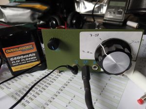
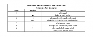 Fig 2 is a picture of a typical morse key and sounder unit that would be used in telegraph offices throughout the world. A video and sound recording of a morse key and telegraph sounder receiving American ( a.k.a. Railroad ) Morse Code can be found here
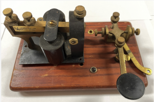
Figure 2: Morse Key and Sounder
I also found an interesting American Morse Code demonstrator on the internet from Morse Code World . You can select letters from a table and hear what it sounds like on a Telegraph Sounder or CW Oscillator.
International Morse Code was standardised in the 1860’s to suit European telegraphy needs and replaced American Morse Code. In later years it became better suited to audible, consistent-tempo signalling using an oscillator, whereas American Morse mostly stuck with the click of a mechanical sounder
With the invention of the thermionic valve, in the early 1900’s enabling the invention of the oscillator, we can assume that electromechanical sounders and resonators would have still been in use at a time when this Elliot Bros GPO key was made. In fact, we know that sounders stopped being used for commercial telegraphy as late as the 1940’s as telephony networks expanded and teleprinters came into service.
Listening to the Sounder demonstration video, I wondered how long it would take to become proficient in sending and receiving with a sounder. I asked the question of Google and it said, “becoming proficient as a telegraphist using a sounder typically took 3 to 6 months of intense daily practice in the late 19th and early 20th centuries. While beginners could memorize the Morse code alphabet in a few hours, training their ears to distinguish the rhythmic “tap, tap, tap” of the sounder and achieving working speeds of 15–20 words per minute required significant dedication, often involving long hours of apprenticeship, especially for noisy environments like railroad stations.”
Apparently, the best operators could translate the sounder’s clicks into written text immediately, sometimes typing messages directly onto a typewriter whilst receiving.
In the UK, in the GPO, there was a career hierarchy within the Telegraph office with boy or girl Messengers becoming Sorting Clerks, then Probationary Telegraphists for up to a couple of years before becoming an Established Telegraphist. The man responsible for the Telegraphy office was called the Superintendent Telegraphist.
The development of UK telegraphic networks saw a shift from private commercial ventures in the 1840s to a unified, Government owned, nationalized service operated by the General Post Office (GPO) by 1870. The GPO expanded the telegraphic service nationwide, utilizing railway lines for infrastructure and providing competitive services until competition from telephone networks reduced its usage throughout the 20th century. At its heyday there were some 14,000 telegraph offices in UK towns and cities.
Looking through some family photographs from the 1890’s, I was surprised to find a picture of Great Grandad Pettitt in his role as a Telegraphist in the Main Birmingham Telegraphist office in Exchange Chambers, Corner of New Street and Stephenson Place.
Talk about it running in the family !!
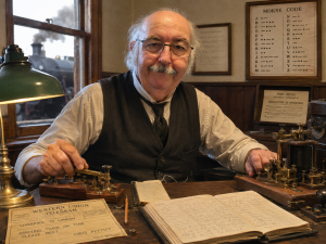
An extraordinary likeness.. Great Grandad Pettitt at work in the 1890’s
73
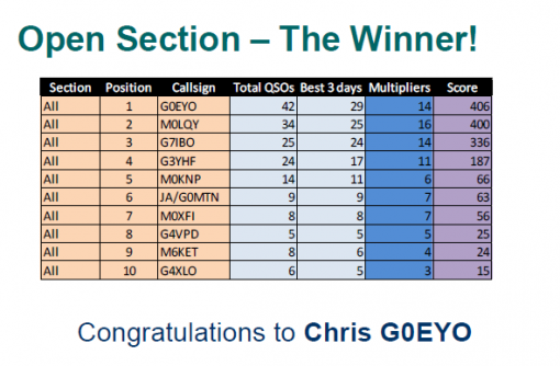
Chris G0EYO


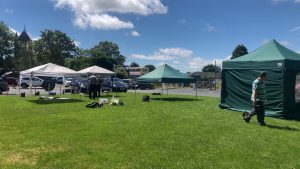
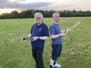
 See Wythall Radio Club members operating via satellite and short wave radio at
 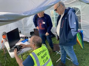 Visitors of all ages are welcome.
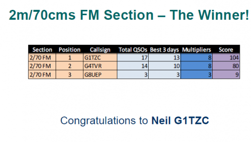
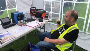
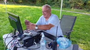
 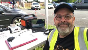 Neil G1TZC, Wythall Radio Club’s enthusiast for using the QO100 geostationary satellite, recently took a trip to Guernsey. Of course, he took his portable satellite station and the Club’s dish with him. Here’s his report on his dxpedition.
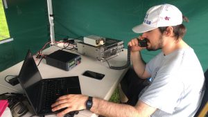
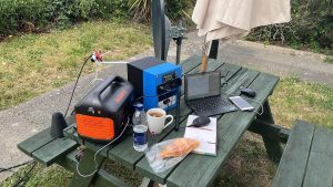 During the week there was time for three stints on the air under the GU call. 101 contacts were made in about three hours on air. Highlights included UAE, Iraq, Brazil and the Balearic Islands.
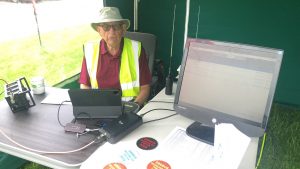
 It was a little bit of a maze, but my ears were able to home in on the faint sound of HF in the distance. Following the sound, a person was eventually found. “Hi, I’m Keith – GU6EFB”.
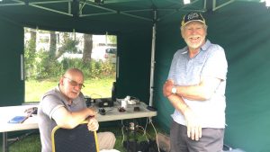
 And chat afterwards in the bar of Wythall House.
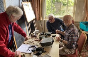
 Just the job for a little refresher or first time soldering and coil winding – there will be expert helpers on hand to advise where necessary!