G7IBO and the Repair of the FT- 817. David submits the FT-817 to a full forensic interrogation.. and he is not a man to be defeated!!
GEEZ A JOB- I CAN DO THAT!
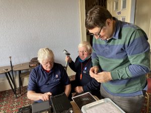
David G7IBO, the author, on the right.
I really enjoy fixing stuff. I had fixed almost everything I had picked up from rallies, ebay etc. so I was a bit bored and wondered if I could get something else to fiddle with. Be careful what you wish for….
Pete (M5DUO) had a ATU which had not been working for months and I’d said that I would have a look at it. One quick look and it was obvious what the problem was. There was a resistor array that had split in two. I replaced this and it was fixed – easy peasy. Pete was well pleased.
Phil (2E0WTH) then suggested that I take a look at Pete’s FT-817. Bolstered by my success I agreed. I then discovered that it had been with a real service engineer for 9 months after which it had been deemed BER (beyond economical repair). This was going to be more of a challenge! However, I reasoned, that only meant that it required too much of the engineers valuable time to track down the fault. I thought I might as well have a go. Little did I know…..
FIRST FAULT
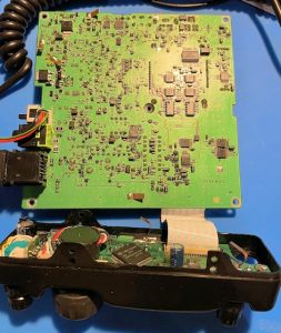
The board of the 817
There was no audio. Nothing out of the speaker and nothing out of the 3.5mm jack connected to headphones or speaker. This was a bit weird because the radio seemed to be receiving fine according to the lcd display, the squelch looked as if it was working AND there was a beep with various keypresses.
I looked at the audio amplifier chip. Seemed ok but no audio signal. I traced the path back through a pre-amp and a multiplexer and bingo, there was the audio signal. The control line to the multiplexor had a couple of inputs, one of which was a MUTE line. Ah-ha, I thought. I traced this all the way back to the main processor and all seemed intact. After much searching and head scratching I discovered that I was wrong. Pin 97 (of 100 around a 1cm square processor) had a bad solder joint. After much cursing I managed to correct the problem and the audio came to life. Receive fixed. Brilliant!
SECOND FAULT
I thought I had seen a glitch in the screen earlier and had asked Pete if this had been the case. It had been OK up to now but the display almost disappeared after the previous fix. Mmmm…I looked at the processor more closely and finally found a loose connection somewhere on the opposite diagonal to the original faulty pin. after more soldering and cursing – fixed
THIRD FAULT
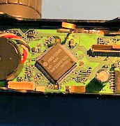
Fixing the main processor and a bad solder joint.
Now to the TX side. There was no power out on transmit. The dealers had thought that the Finals Board had gone so I took a look. I noticed that there was no power to the PA board or the Finals. A surface mount fuse had blown on the line supplying both these boards. After much debate and further probing I decided to take a chance and just bypass the fuse. I waited for the bang! Phew, it seemed ok. But still no power out.
FOURTH FAULT
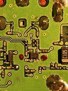
Amplifier Q1007 (dual gate MOSFET)- faulty and in need of replacement
I found the first IF 68.33MHz and thought I’d start where it combines with the transmit IF signal. There is an amplifier Q1007 (dual gate MOSFET) to provide gain and its also where the ALC and VSWR protection can adjust the output. The mosfet had a short circuit on the output. I determined that it was faulty and removed it. The short had disappeared from the output terminals. I was relieved as I had burned my boats. I needed a new component and fortunately Yaesu UK were able to help. They could provide the part and very kindly sent it for free (its a 1mm square surface mount thingy). Thanks Yaesu. A week later I replaced the part and hoped that the power out would be restored – no such luck. There should be power to the MOSFET. There was none. More investigation required.
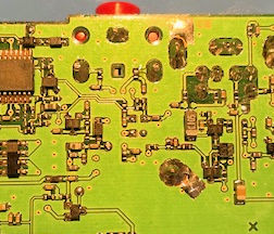
More investigation required
FIFTH FAULT
Having found the Amplifier to be without power ONLY ON TX I began to wonder if there was some inhibitory circuit switching off the power. Indeed there was. If the reflected power was high (high SWR) a transistor switched the power line to earth. In fact there was another line, AFP (which I found out was Automatic Finals Protection) which also caused the power to be routed to earth. I had to prove my theory so I had to provide power to the MOSFET somehow. I suspected that the AFP line should be high to allow transmission and on pulling pin 6 of Q1098 High (5v through 1k resistor) I found that the transmitter burst into life. A full 5w of power on top band FM – WOWSER!!! In fact it gave out full power on all bands.
This was brilliant. Not only had I confirmed my theory, but I had fixed the transmit side and proved that the FINALS were intact. That makes this whole project a damn site cheaper :-)
Now, all I had to do was figure out how why the protection systems were kicking in?
The REV (reflected power) line had a voltage on it but it didn’t seem high enough compared with the FWD line. The AFP line was at 0v but I didn’t really know what that meant. And I noticed that when I transmitted the SWR on the display was high on the front antenna (7bars) but full (9bars) and an HSWR showed on the rear antenna. This lead me on to a long search for a reason for this high SWR. The really weird thing was that it did not matter if a carrier was present or not (FM or CW or SSB mode), the HSWR would always be present. The other thing that lead me to believe that this was spurious was the fact that I was able to get full power out on all bands with my power bypass bodge.
The AFP line came from a chip (Q1077) that was directly controlled by the central processor via a serial link. With my previous problems with bad joints on the processor I tried to relate the problem to that. Nah, unfortunately that wasn’t it.
The processor controlled the AFP in response to a high SWR but the REV line didn’t go to the processor, a D/REV line did. I discovered a multiplexor chip which took REV and FWD and sent them to the processor via the D/REV and S/FWD lines (switching between DISCRIMINATOR/REVERSE and S(ignal)/FORWARD on Rx vs Tx. Could this chip be at fault. I looked at the voltages on all the pins and the one for D/REV did not look right at all. The input on Tx did not match the output (0.8v vs 3.6v). The chip must be bad. I was just just about to remove it and order a new one when I took another look. The voltage on the D/REV line almost matched that on the N/ALC line. There was clearly a short between the two. Still thinking the chip was bad I went for a cup of tea and a good think. Both of these lines went to the central processor (on the front panel) via a 50 way ribbon cable. Now suspecting that the short may be on my old friend the CPU I disconnected the ribbon and as surmised the short across the multiplexor chip disappeared. Getting there.
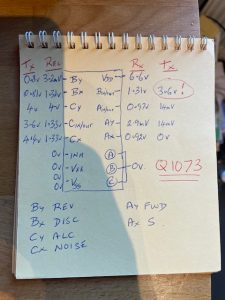
David’s helpful notes on this journey
The D/REV and N/ALC lines on the front panel PCB were adjacent to each other at two places. Firstly at pins 34 and 35 of the large ribbon connector then at pins 80 and 81 of the the CPU. I confirmed that there was a short between the lines but at which end? The track between the two possibilities disappeared into the multilayer board. However, I could get to both ends to test the connections. Checking it with a multi-meter did incur some risk to the CPU but I didn’t have much choice. A good trick is to measure the short at both the CPU and ribbon connectors and see which has the lowest resistance. The ribbon cable end won (0.2ohms vs 0.5ohms). The short proved elusive but by poking a thin wire under the connector I must have managed to dislodge something as eventually the short disappeared. For the hundredth time I put the radio back together. It had worked! Full power on all bands. At last! I could take it back to Pete in triumph that evening!
BUT WAIT… Oh no. The Front panel was showing good SWR as expected but was unfortunately only partially displaying. I know what that is – no it wasn’t. I ended up taking the whole front panel apart (bad idea) but only succeded in in loosing the display altogether. After much cursing and searching the internet I came to the conclusion that the only way to fix this problem was to get a new LCD screen.
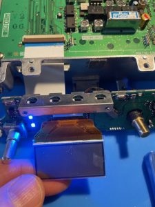
The new screen and,at some cost .. but worth it
Really disappointing considering I thought I was done a few hours earlier. And then it got worse. You can’t buy the LCD screen on its own. You have to buy the the front panel PCB at the cost of £163 from Radioworld (£202 from Yaesu!). This was really frustrating considering that most of the problems had arisen and had been fixed on the original front panel PCB.
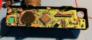
The front panel laid bare
I had a discussion with Pete and he said he would go ahead and buy the new PCB if I was still willing to install it. I was only too willing to do this as it was a relatively simple task and I was confident that I could then present Pete with a working radio.
The PCB was complete except for the need for a connector to be soldered to the old AF-SQL/RF control. The tuning control just plugged in to the board, ribbon cable connected and there you go.
ARGHHHHH…….. The display was blinking, there was no audio, the Tx/Busy light didn’t work with squelch and there was no transmit (Tx ERR displayed) after a brief red TX/Busy light.
Maybe it was arrogant of me to think that I could have any chance of fixing this monster. I am on to the sixth individual fault now and I’m running out of hair to pull out. But, I have spent money on it now so I will continue until it and the wall become very good friends. Wish me luck and any helpful suggestions will be gratefully received.
David G7IBO

