wythall radio club

having fun with RF
Subscribe

Archive for the ‘Club’

6 MONTHS OF WYTHALL RADIO CLUB A CTIVITY JANUARY TO JUNE

January 14, 2025 By: john daws Category: Club, News

 PROGRAMME FOR WYTHALL RADIO CLUB  JANUARY 1ST– JUNE 30TH 2025

  Other Events to be added and announced


Tuesday January 14th 8.30 Open Committee meeting .

 Tuesday January 21st. 8.30 Xmas Contest Results.

Friday January 24th 9.45-11.45   Practical/Operating/problem solving : the Darts Room


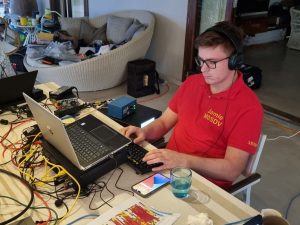
Tuesday February 4th 8.00 M0SDV on the DXpedition to Guyana 8R7X

Friday February 21st 9.45-11.45 Practical/Operating/Problem Solving in the Darts Room.


Tuesday March 4th 8.30 Ask the Experts- Round the Table Q & A Session

Friday 21st March 9.45-11.45 Practical/Operating/Problem Solving in the Darts’ Room


Tuesday April 1st. 8.30 Open Committee Meeting

Thursday April 17th-Monday 21st April The Famous Wythall Radio Club Easter Contest

Friday 18th April 9.45-11.45 Practical /Operating /Problem Solving in the Darts’ Room

( rearranged to accommodate Good Friday)


May –SOTA sessions to be announced

Tuesday May 6th 8.30 Easter Contest Results.

Saturday May 10th : Open shack day: Neil G1TCZ

Friday May 23rd 9.45-11.45 Practical/operating /Problem Solving Session in the Darts’ Room.


Tuesday June 3rd 7.30 onwards: Foxhunt in the Park and DIY activities.

Tuesday 10th June 7.30 pre G0BUS meeting in Bar.

Friday 13th June 9.00 a.m. meet WRC  to collect gear and  Transport Museum set –up

Saturday 14th 9.00 Wythall transport Museum Activation G0BUS

Friday 20th June 9.45-11.45 Practical/Operating /problem solving: The Darts Room.


THE CLUB MEET SOCIALLY EVERY TUESDAY EVENING AT WYTHALL HOUSE  AT  7.30 P.M.

How Low Can You Go??.. The New Year Challenge

January 03, 2025 By: john daws Category: Club, Fun

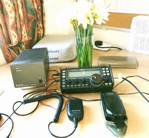
The K2 ready to go .. no wasted power there and heading for 14060

Members of Wythall Radio Club limber up for the January challenge ( note the dress code!)

THE JANUARY 2025 WYTHALLRADIO CLUB QRP(P) MONTH.

Not contest .. just a challenge to work in whatever mode .. reduce the power.. push the boundaries..and let fellow members know of your experiences.. best bands .. antennas used and of course the power.


Lee has set up the DXCC QRP ladder  and comment board so we can all learn of  each others successes and, as a bonus,  the current World Wide Award (WWA) activity can provide extra stimulus. Good luck!!


The 817 saga continued: Ian M0IDR recalls a previous challenge

December 26, 2024 By: john daws Category: Club, Fun

      The mighty FT 817

I will if I may recount fairly  briefly a tangle I had with the 817 from Vic (SK)  Mostly mechanical issues as opposed to electronic component  failures RECEIVE AUDIO or rather LACK OF.

I was so captivated in reading David’s fault chasing in Pete’s FT817, component level fault finding at its  best!

Many Congratulations David- hope the final issue is resolved.

The rig was a early one which  originally had the limited transmit range on for example the 40m band. It had been opened and extended and that is where the problems began.

Clearly working fine for Vic, it gave no audio output although like Pete’s it gave audible beeps upon key depression.

Top cover removed restored full audio, just placing the cover back without securing it gave full audio but re-inserting the fixing screws  and inverting the unit cut the audio! Upside down- no audio, right way up- Audio! 

With the lid  fully unscrewed by trial and error, the issue was narrowed down to just one mounting screw causing the audio to cut out. Leaving that pesky screw out (Front right hand side) you could position it anyway and it was fine!

The screw in question must be shorting something to ground, nothing appeared obvious. Close examination showed that screw to be fractionally longer by two thread pitch so  I filed a microscopic amount off the screw- job done ..or so I thought.

DC CONNECTOR ISSUE

Next problem: the well-known and documented dc plug to socket intermittency.  Whilst the  plug can be obtained it is usually the pcb mounted socket at fault. ‘Unobtanium’ of course so bodge (a safe bodge I hasten to add) was to sleeve the dc plug with the thinnest  metal I could find- actually of another dc type plug with a wider barrel. This gives enough barrel to (worn) contact to restore happiness to the user.

“Job a goodun”.. Unless of course the user disconnected the dc power lead in which case the bodge most likely would fell apart- literally leaving the sleeve behind.

As the rig was to go to a purchaser I fitted a permanent connector into which the original dc lead fitted. I consider the purchase of one of these dc adapters to be a sound investment for the 817 and 818 which used the same ‘unobtanium’ socket for dc power. Two versions are shown, one twice the cost of the other but protection of the rather fragile dc connector is ensured. Both fix to the rig by the screw that previously gave a chassis earth connection. Existing DC lead fits or Power Pole to suit.

Please Note:

Both types do however impede the proper  fitting of the Yaesu vinyl protection cover.

DISPLAY FADE

Lastly the display with moderate  panel movement partially faded and the right hand side  was unreadable.  

When this rig had been wide-banded by ANOther, the very fragile cable pcb to display ribbon cable had been over stressed and   was held together with a touch of blu-tack!   Where the ribbon cable is inserted in the connector it is push fit-no clamp and had to be cleaned of all the blue gunge. Fortunately all was well when it had been treated.

You do  need to take great care with these  ribbon cables which are essentially pcb tracks on thin acetate or similar.

Ian M0IDR

Ed. we await David’s (G7IBO) next instalment of  his journey to  get the 817 working again.


GOOD LUCK TO ALL IN THE FAMOUS WYTHALL RADIO CLUB XMAS CONTEST 2024.

THIS IS NOW, FROM 10.00 A.M. THIS MORNING , UP AND RUNNING


G7IBO and the Repair of the FT- 817. David submits the FT-817 to a full forensic interrogation.. and he is not a man to be defeated!!

December 10, 2024 By: john daws Category: Club, Fun

GEEZ A JOB- I CAN DO THAT!

David G7IBO, the author, on the right.

I really enjoy fixing stuff. I had fixed almost everything I had picked up from rallies, ebay etc. so I was a bit bored and wondered if I could get something else to fiddle with. Be careful what you wish for….

Pete (M5DUO) had a ATU which had not been working for months and I’d said that I would have a look at it. One quick look and it was obvious what the problem was. There was a resistor array that had split in two. I replaced this and it was fixed – easy peasy. Pete was well pleased.

Phil (2E0WTH) then suggested that I take a look at Pete’s FT-817. Bolstered by my success I agreed. I then discovered that it had been with a real service engineer for 9 months after which it had been deemed BER (beyond economical repair). This was going to be more of a challenge! However, I reasoned, that only meant that it required too much of the engineers valuable time to track down the fault. I thought I might as well have a go. Little did I know…..

 FIRST FAULT

The board of the 817

There was no audio. Nothing out of the speaker and nothing out of the 3.5mm jack connected to headphones or speaker. This was a bit weird because the radio seemed to be receiving fine according to the lcd display, the squelch looked as if it was working AND there was a beep with various keypresses.
I looked at the audio amplifier chip. Seemed ok but no audio signal. I traced the path back through a pre-amp and a multiplexer and bingo, there was the audio signal. The control line to the multiplexor had a couple of inputs, one of which was a MUTE line. Ah-ha, I thought. I traced this all the way back to the main processor and all seemed intact. After much searching and head scratching I discovered that I was wrong. Pin 97 (of 100 around a 1cm square processor) had a bad solder joint. After much cursing I managed to correct the problem and the audio came to life. Receive fixed. Brilliant!

SECOND FAULT

I thought I had seen a glitch in the screen earlier and had asked Pete if this had been the case. It had been OK up to now but the display almost disappeared after the previous fix. Mmmm…I looked at the processor more closely and finally found a loose connection somewhere on the opposite diagonal to the original faulty pin. after more soldering and cursing – fixed

THIRD FAULT

Fixing the main processor and a bad solder joint.

Now to the TX side. There was no power out on transmit. The dealers had thought that the Finals Board had gone so I took a look. I noticed that there was no power to the PA board or the Finals. A surface mount fuse had blown on the line supplying both these boards. After much debate and further probing I decided to take a chance and just bypass the fuse. I waited for the bang! Phew, it seemed ok. But still no power out.

 FOURTH FAULT

Amplifier Q1007 (dual gate MOSFET)- faulty and in need of replacement

I found the first IF 68.33MHz and thought I’d start where it combines with the transmit IF signal. There is an amplifier Q1007 (dual gate MOSFET) to provide gain and its also where the ALC and VSWR protection can adjust the output. The mosfet had a short circuit on the output. I determined that it was faulty and removed it. The short had disappeared from the output terminals. I was relieved as I had burned my boats. I needed a new component and fortunately Yaesu UK were able to help. They could provide the part and very kindly sent it for free (its a 1mm square surface mount thingy). Thanks Yaesu. A week later I replaced the part and hoped that the power out would be restored – no such luck. There should be power to the MOSFET. There was none. More investigation required.

More investigation required

 FIFTH FAULT
Having found the Amplifier to be without power ONLY ON TX I began to wonder if there was some inhibitory circuit switching off the power. Indeed there was. If the reflected power was high (high SWR) a transistor switched the power line to earth. In fact there was another line, AFP (which I found out was Automatic Finals Protection) which also caused the power to be routed to earth. I had to prove my theory so I had to provide power to the MOSFET somehow. I suspected that the AFP line should be high to allow transmission and on pulling pin 6 of Q1098 High (5v through 1k resistor) I found that the transmitter burst into life. A full 5w of power on top band FM – WOWSER!!! In fact it gave out full power on all bands.

This was brilliant. Not only had I confirmed my theory, but I had fixed the transmit side and proved that the FINALS were intact. That makes this whole project a damn site cheaper :-)
Now, all I had to do was figure out how why the protection systems were kicking in?

The REV (reflected power) line had a voltage on it but it didn’t seem high enough compared with the FWD line. The AFP line was at 0v but I didn’t really know what that meant. And I noticed that when I transmitted the SWR on the display was high on the front antenna (7bars) but full (9bars) and an HSWR showed on the rear antenna. This lead me on to a long search for a reason for this high SWR. The really weird thing was that it did not matter if a carrier was present or not (FM or CW or SSB mode), the HSWR would always be present. The other thing that lead me to believe that this was spurious was the fact that I was able to get full power out on all bands with my power bypass bodge.

The AFP line came from a chip (Q1077) that was directly controlled by the central processor via a serial link. With my previous problems with bad joints on the processor I tried to relate the problem to that. Nah, unfortunately that wasn’t it.
The processor controlled the AFP in response to a high SWR but the REV line didn’t go to the processor, a D/REV line did. I discovered a multiplexor chip which took REV and FWD and sent them to the processor via the D/REV and S/FWD lines (switching between DISCRIMINATOR/REVERSE and S(ignal)/FORWARD on Rx vs Tx. Could this chip be at fault. I looked at the voltages on all the pins and the one for D/REV did not look right at all. The input on Tx did not match the output (0.8v vs 3.6v). The chip must be bad. I was just just about to remove it and order a new one when I took another look. The voltage on the D/REV line almost matched that on the N/ALC line. There was clearly a short between the two. Still thinking the chip was bad I went for a cup of tea and a good think. Both of these lines went to the central processor (on the front panel) via a 50 way ribbon cable. Now suspecting that the short may be on my old friend the CPU I disconnected the ribbon and as surmised the short across the multiplexor chip disappeared. Getting there.

David’s helpful notes on this journey

The D/REV and N/ALC lines on the front panel PCB were adjacent to each other at two places. Firstly at pins 34 and 35 of the large ribbon connector then at pins 80 and 81 of the the CPU. I confirmed that there was a short between the lines but at which end? The track between the two possibilities disappeared into the multilayer board. However, I could get to both ends to test the connections. Checking it with a multi-meter did incur some risk to the CPU but I didn’t have much choice. A good trick is to measure the short at both the CPU and ribbon connectors and see which has the lowest resistance. The ribbon cable end won (0.2ohms vs 0.5ohms). The short proved elusive but by poking a thin wire under the connector I must have managed to dislodge something as eventually the short disappeared. For the hundredth time I put the radio back together. It had worked! Full power on all bands. At last! I could take it back to Pete in triumph that evening!

BUT WAIT… Oh no. The Front panel was showing good SWR as expected but was unfortunately only partially displaying. I know what that is – no it wasn’t. I ended up taking the whole front panel apart (bad idea) but only succeded in in loosing the display altogether. After much cursing and searching the internet I came to the conclusion that the only way to fix this problem was to get a new LCD screen.

The new screen and,at some cost .. but worth it

Really disappointing considering I thought I was done a few hours earlier. And then it got worse. You can’t buy the LCD screen on its own. You have to buy the the front panel PCB at the cost of £163 from Radioworld (£202 from Yaesu!). This was really frustrating considering that most of the problems had arisen and had been fixed on the original front panel PCB.

       The front panel laid bare

I had a discussion with Pete and he said he would go ahead and buy the new PCB if I was still willing to install it. I was only too willing to do this as it was a relatively simple task and I was confident that I could then present Pete with a working radio.

The PCB was complete except for the need for a connector to be soldered to the old AF-SQL/RF control. The tuning control just plugged in to the board, ribbon cable connected and there you go.

ARGHHHHH…….. The display was blinking, there was no audio, the Tx/Busy light didn’t work with squelch and there was no transmit (Tx ERR displayed) after a brief red TX/Busy light.

Maybe it was arrogant of me to think that I could have any chance of fixing this monster. I am on to the sixth individual fault now and I’m running out of hair to pull out. But, I have spent money on it now so I will continue until it and the wall become very good friends. Wish me luck and any helpful suggestions will be gratefully received.

David G7IBO

Restoring the Pye EK106 Telegraph Key

December 03, 2024 By: john daws Category: Club, Fun, News

 OR…. ‘ CONFESSIONS OF A JUNKEY’!!

             Chris in his workshop

My name is Chris G0EYO and I am an addict!

My problem is fairly recent,  but I have to say I never saw it coming.

It started with a desire, after holding an amateur licence for 40 years, to try and master CW, having enjoyed SSB and FT8. My inspiration was fellow club member and Chairman, John M6KET. His dedication to amateur radio using only CW and QRP powers, kept reminding me of the true origins of this great hobby of ours.

I had learnt to receive morse some 60 years ago having been a trainee GCHQ Intercept Operator at Bletchley Park, but was never required to send it. With John’s help and encouragement, I slowly picked up my sending speed, first with an ordinary Hi-Mound straight key and then with an old Kenpro Electronic paddle.

I bought a vintage Japanese Ameko K-4 telegraph key from a club member’s SK sale and I sold the Hi Mound to John M6KET.

Then in February 2024 I saw a collection of morse keys for sale in a Midlands auction and bid on and won those. Amongst them was a couple of lovely Kent Heavy brass straight keys and a rather battered Vibroplex Champion, which I restored. But, even then, I wasn’t satisfied.

I saw another lot morse keys in a recent auction in Newcastle which included a rather nice Marconi NATO morse key and several other interesting keys. I bid on those and won them. Amongst the lot was a rather plain, GPO  type, telegraph key made by W.G. Pye of Cambridge.

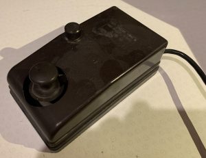
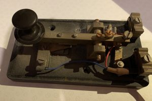
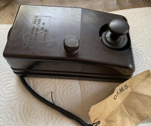
The EK106 before Chris got to work (and pictured below left))

 It was very tarnished and in need of some TLC. I did a bit of research and discovered that these keys could be quite rare, but of good quality, being solid brass on a Bakelite base. It has a serial number of EK106. Others with similar serial numbers are known; viz, EK107 (in the Brundit collection) and EK105 ( in the G0RDO collection).

The Telegraphkeys.com website identifies this key as probably being manufactured between 1913 and 1929. W.G. Pye & Co was originally a scientific instruments manufacturer.  Out of that company was spun the famous Pye Radio Company, now part of Phillips  Group.

 Whenever I do a key restoration, I take lots of pictures of how the key is put together, I then mark up a couple of prints and number the main parts, especially the fixings. I then mark up small plastic bags to put the  relevant parts in as I disassemble it. There are many ways to clean brass. My preference is to use Brasso metal polish with a very fine wire wool. Once the oxidation tarnish is removed, I buff the item with a Dremel buffer tool. Bakelite can also be cleaned up with Brasso but instead of wire wool I use a soft cotton wool pad. I give all parts a final clean over with a microfibre cloth.

This particular key presented few difficulties when it came to taking it apart. The retaining hexagonal nuts on the underside were tight in on the recess preventing a box spanner being used.

The nuts had a slot in them and fortunately I had a screwdriver bit known as a “snake bit” in my tool box which did the job.

Having stripped the key down, I cleaned up the base and key knob, which were both made of bakelite. Each of the various brass parts were cleaned and buffed. The tension spring looked rather rusty so I decided to find a replacement. Amazon came up trumps but I don’t think it has the same tension characteristic as the original although the same size. If I do sell this key I will include the original spring with the replacement so that the purchaser can fit it if they so wish.

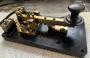
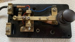
THE FINISHED AND BEAUTIFULLY RESTORED PYE EK106 STRAIGHT KEY

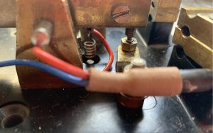
AN EYE FOR DETAIL IN THE PYE EK106


THE RESTORED KEY LOOKS RATHER NICE . I HAVEN’T USED IT IN ANGER YET BUT HOPE TO DO SO BEFORE SELLING IT ON.

CHEERS AND 73’S

CHRIS G0EY0

The Friday Morning Club

November 17, 2024 By: john daws Category: Club, Fun, News

All roads led to the operating room at  Wythall House recently as The Friday Morning Club met again after a long absence.

With the 240’ doublet in action David G7IBO was able to see if his recently assembled QRP lab QMX mini transceiver would come to life and  with John M6KET  on hand (and using David’s home-made paddle) worked Nigel G4BSW  on 40m with 5 watts..  (THE QMX ? -an excellent little radio with crystal clear audio).

Winston looks on as David inspects Phil’s operating table

David shows his delight at the first QSO made with the QRP Lab QMX transceiver

In a quiet corner Chris G3YHF was anxious to try the Club’s 6m beam  and rotator and enjoy the recent excellent conditions on this band: alas the conditions did not cooperate on Friday morning but contact was made with fellow member Martin G8VXX/M on his canal boat at the Black Boy Pub in Knowle, Warwickshire, via GB3WL and 2m FM. And half a QSO with an EI on 2m ft8.!

6m not responding but Chris able to contact Martin G8VXX on 2m

  On another table Phil 2E0WTH assembled his carefully thought out rig- in- a box and magnetic loop and Martin 2E0XFI brought in his very neat Icom 705 and lap top to try the magnetic loop on ft8.

Neil and Debra popped in to say hello. (Perhaps some satellite operation next time ??!)

Witnessing this hive of activity was Winston 2E0EGP  and Neil G1TCZ and Debra.

Neil’s account of his help in tracking the escaped  Gyrfalcon can be seen in the recent edition of Radcom.

With the success and support for  this opening of the Club on a Friday morning it is hoped to make this a regular event , meeting on the third Friday of each month.

Our next meeting of THE FRIDAY MORNING CLUB therefore would be on Friday December 20th

Watch this space for confirmation of date and times.


COMING SOON TO WYTHALL RADIO CLUB

 Tuesday December 3rd Wythall Radio Club on Air 

Tuesday December 10th Xmas Social in the bar

December 26th-21st: the famous Wythall Radio Club Xmas Contest


Talk on LF operating – this Tuesday 5th Nov.

November 01, 2024 By: Chris G3YHF Category: Club, Fun, News, Training

What’s happening at the low frequency end of the amateur spectrum?

Dave Pick, G3YXM, RadCom’s LF correspondent, will be revealing all on 5th November at 8.30pm, Darts Room, Wythall House.

All welcome. 

Have some refreshment at Wythall House bar before and after the event.

This is just one of the features in Wythall Radio Club’s new 12 month programme now available here – and on right hand side of our home page.

We’ll post updates as events are added and finalised.  

Photo of Droitwich aerial system courtesy of an anonymous rigger in late 1960s – source and more info here

A year in the Life of Wythall Radio Club: The Chairman’s Report

October 27, 2024 By: Chris G3YHF Category: Club, Fun, News

Chris , retiring chairman,  with Lee at a sunnier Plug and Play event.

 THE CLUB HAS HAD ANOTHER BUSY YEAR

After last year’s AGM we published a programme of activities for the year ahead.  This was added to and adapted during the year.  It helped us make sure there was something of interest for members each month, usually on the first Tuesday – and sometimes we had several activities in a month!

 THE PROGRAMME FOR THE YEAR AHEAD IS ALREADY UP ON THE WEBSITE

I think the biggest development this year was our ‘August Tuesday evenings on the lawn’ – trying out antennas, learning to use a nanoVNA, operating radios, nattering and generally having fun.  This even encouraged some members we hadn’t seen for some time to come along.

Like all good ideas, this emerged from our members – a couple of members wanted try out some antennas, and after the first night we just carried on for the next couple of weeks taking advantage of the fine weather!  It provided an ideal opportunity to try out the vertical antenna kindly donated by Chris G0EYO.

Ian M0LQY adjusts one of the guys our ‘new’ Cushcraft vertical (Thanks to Chris EYO)

Sadly, the weather wasn’t so kind to our big public events – Museum on the Air weekend at Transport Museum Wythall, Plug and Play (which had to be postponed due to a downpour) and the Stoke Prior Steam Fair.  We also struggled to find enough members and transport to renew our involvement with the Steam Fair. 

The Steam Rally team damp but determined and cheerful

However good team-work and commitment meant that we were able to provide a high-quality demonstration of amateur radio in the two events that did run.  Having two HF stations and the satellite station plus occasional VHF operational during these events provides a lot of interest but also means individual members don’t have to be on duty all the time.

Other new developments during the year include John 2E0XET and Clive M0KNP’s club SOTA expedition to a very misty Titterstone Clee Hill, and Neil G1TZC and Debora’s work in putting together 70cm beam kits for the foxhunt in the park.  The Q and A round table was also positively received by members.

Neil with his immaculately presented Fox Hunt table .. thanks too to Debra

The web-site has been very busy under John 2E0XET’s editorship and with contributions from seven members.  I counted an impressive 42 posts over the last 12 months – all good publicity for the Club.  It’s great to have the occasional post from our DX member Kev G4XLO in Devon, and also his regular contribution to our weekly DX table round-up.

It’s very important for the future of the Club to be able to attract new members, and we welcomed 6 new members 12 months ago plus Garry ZD7GWM as an overseas member.  They’ve immediately become part of the life of the Club.  They bring skills and expertise that help us to ‘have fun with RF’, as our motto says. 

I’d particularly like to thank Garry for being willing to pop up on the satellite when we run events to amaze our visitors with the clear signal from St. Helena, leaving them puzzled as to why we can do this but the wifi in their own house is so poor!

Balmy summer evening activity on the ‘lawn’ out side Wythall House

One of the strengths of our Club is that members are fully involved in planning our activities.  I must admit when I first joined the Committee back in about 2014 I couldn’t understand why it didn’t meet on it’s own to plan events as usually happens, but I can see now that our Open Committee meetings set the tone for all members to be able to shape what the Club does and keep it active and developing.

I’m standing down this at this AGM after three years as chairperson.  It’s been an honour to hold this position and to work with members to help the Club move forward from the challenges of the Covid  lockdowns, reduced membership and a tighter financial base. 

I’d like to thank members for their suggestions and participation, and especially the Committee – John, Clive, Pete, Ian Reeve, and Ian Gilmore.  We’ve had to address such issues as the cellar rooms, the perpetually rotating beams, the Hamfest, the 30 years-worth of accumulated gear, and relations with the House.


COMING SOON: TUESDAY NOVEMBER 5TH THE DARTS ROOM. 8.30 PM

  THE LF BANDS WITH DAVE PICK G3YXM. 

Dave G3YXM operating at the Wythall Transport Museum Activation


That Recognisable Fist- The CW operators’ fingerprint

October 13, 2024 By: john daws Category: Club, Fun

THE OPERATORS FIST CHRIS G0EYO EXPLORES THE CLANDESTINE WORLD OF WORLD WAR II CW OPERATORS .

Many of us will have read the stories of W/T operators during WW2 being recognisable by their style of sending, otherwise known as the Operator’s Fist or Fingerprint. In a book I have just read about Code Writing and Code Breaking in the S.O.E *. by Leo Marks, ** he explains at some length why it was important to be able to recognise the operator at the other end of the link. Agents sent into Europe by SOE often had a W/T operator accompanying them. According to Marks, W/T operators fell into two categories; those who sent from the wrist and those who sent from their elbows.

Apparently, the elbow senders where more consistent in their sending than the wrist senders. The operator’s receiving the W/T traffic (known as” Signal Masters”) had to distinguish between errors caused by “stress” or “morse cramp” – colloquially known as “morse mutilation”; (don’t forget,these agents are sending under extreme pressure. Germans with D/F vehicles were constantly hunting for them), or errors caused by the changing propagation, or “atmospherics”.

The Signal Masters could always distinguish between mis-transmitted groups and  morse mutilated ones for a very simple reason: poor atmopheric conditions affected all the code groups, often making the clear-text impossible to read, whereas an operator’s mistake affected only individual letters

Type 3 MK II otherwise known as the B2. The UK version of the Spy Radio. Image reproduced by kind permission of the owner Steen Wichmand OZ8SW


S.O.E. realised that the W/T operator’s touch on the keyboard was as individual as a fingerprint. so detailed recordings were made of every operator’s “fist” before he or she left for the field. The operators were instructed to transmit every letter of the alphabet at varying speeds, followed by every numeral, but were given no warning that they were being “fingerprinted” to avoid self-conscious transmissions. Their dots, dashes and Morse hesitations were then transferred to a paper tape which moved at 16 feet per minute. This magnified even the smallest Morse dots by quarter of an inch, allowing an in-depth study to be made of every operator’s style. The  on square-ruled paper and lodged with the chief Signal Masters at the WT stations.

When the operators reached the field, their “fists” varied from message to message, responding to the tensions of the moment, but the basic characteristics were always present. Eventually the Signal Masters needed no fingerprinting charts to identify these characteristics: their Morse-trained ears were attuned to every nuance of an operator’s touch, and they recognised it at once. The Funk-Horchdienst (the German interception service) was equally adept. Its radio experts were able to counterfeit our operators’ style to perfection if sufficient numbers of messages had been intercepted.

Even so, if an agent or W/T operator had been caught, anyone else sending their messages back to the UK with a different fist would ring warning bells that the agent and/or W/T operator may no longer be free.

USA Suitcase Radio SSTR-1 . made by the Office of Strategic Services: later known as the CIA. Image reproduced by kind permission of the owner Steen Wichmand OZ8SW

The Code-breakers at Bletchley Park also used this “fist “recognition system to track German operators as the units they were attached to, moved from one location to another.


Chris G0EYO
2/9/24


*  (Special Operations Executive – authorised by Churchill to create sabotage and havoc in occupied Europe)
.** Marks, Leo. Between Silk and Cyanide: A Code Maker’s War :1941-45. The History Press.


Activities for next 12 months!

October 05, 2024 By: Chris G3YHF Category: Club, Fun, News

What’s happening at the low frequency end of the amateur spectrum?

Dave Pick, G3YXM, RadCom’s LF correspondent, will be revealing all on 5th November at 8.30pm, Darts Room, Wythall House.

All welcome. 

Have some refreshment at Wythall House bar before and after the event.

This is just one of the features in Wythall Radio Club’s new 12 month programme now available here – and on right hand side of our home page.

We’ll post updates as events are added and finalised.  

Photo of Droitwich aerial system courtesy of an anonymous rigger in late 1960s – source and more info here