wythall radio club

having fun with RF
Subscribe

Archive for the ‘Club’

400+ Squares Worked on 6M in 2021!

January 10, 2022 By: Chris G3YHF Category: Club, Contest, Fun, News

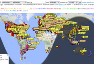
Over 400 squares were worked by Lee G0MTN and Mike G4VPD on 50 MHz during Wythall Radio Club’s 2021 ‘6 meters and up’ Challenge!

The map shows contacts as far apart as Japan and central America!  

Lee achieved 461 squares, just pipping Mike on 447, both making great use of FT8.

Impressive results were also achieved on the other bands.

Mike G4VPD worked 94 and 87 squares on 4 and 2 meters respectively, while Simon G4TVR achieved 18 and 12 squares on 70cms and 23 cms respectively.

Keep tuned to those higher bands during 2022 and see what can be worked!

Lots of DX in Wythall’s Annual DXCC Challenge

January 03, 2022 By: Chris G3YHF Category: Club, Contest, Fun, News

Over 100 countries worked by Wythall Radio Club’s operators in the annual DXCC Challenge 2021!

Tim M0URX came top in the ‘full licence’ section with 148 countries – all on SSB – just ahead of Chris G0EYO, Mike G4VPD and Ian M0LQY with 141, 139 1n 135 countries, all using FT8.

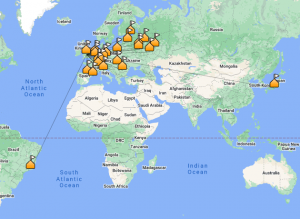
On the left is the map of Tim’s contacts.

So on this occasion, snappy SSB operation got the better of FT8’s weak signal advantages!

There were impressive results in the intermediate and foundation licence sections. 

Kev 2E0NCO caught 72 countries using FT8.

Meanwhile, confirmed QRP and CW op. John M6KET worked 76 countries on the key with a maximum 10 watts to a doublet.  Nice work!

Leading scores this year were lower than in 2020.  Then, the top ‘full licence’ section score was 160 and both foundation and intermediate top scores were 100 or more.  

The difference seems to be that in 2020 leading scorers were often using multiple modes, while in 2021 they stuck to one mode.

With conditions on the higher HF bands improving, lets see what the 2022 challenge can achieve!


Seasons Greetings – and lots of 2022 DX please!

December 25, 2021 By: Chris G3YHF Category: Club, Fun, News

Wythall Radio Club wishes members and friends seasons greetings!On The Antenna Again

Let’s hope for a safe 2022 and continued improvements on the HF bands!

Meantime, Club members will once again be warming up their rigs for our famous Xmas Contest!

73s to all!


PHOTO:  https://www.pauloxmanpublishing.com/On-The-Antenna-Again,12804.html


Autumn Activities at Wythall Club

October 04, 2021 By: Chris G3YHF Category: Club, Fun, News

Wythall Radio Club is meeting in person on Tuesday nights as usual.  Wythall House is the location.

The Club’s monthly activity challenge has restarted after its summer break.

This month 40m is the focus – work as many DXCC countries as you can during October. 


To add interest, members can enter either the ‘classic’ modes section (CW or SSB) or the ‘digital’ section (FT4/8).

Or both if you are keen!


In the first 4 days, over 30 countries have already been worked – including Cuba, Kazakhstan and the USA.


From the Workbench: QRP Labs QCX-Mini

September 22, 2021 By: Chris G3YHF Category: Club, Fun, News

Ian M0IDR and Chris G3YHF have been having fun building this tiny rig.  Here’s how they got on….

The QCX-Mini is a miniature version of QRP Labs QCX+ kit.  Measuring only 95x63x25mm, itQCX-mini 5W CW transceiver compresses the features of its bigger brother in to a tiny box, giving up to 5w CW on any single band between 80 and 17m. 

Photo from http://shop.qrp-labs.com/qcxmini

There are connectors for CAT control and GPS interface as well as the usual power, key, headphones, etc.

Its small size and low power consumption – rated at 58mA on receive with back-light off – means it is ideal to carry in a pocket for /P, SOTA and similar activities.

Chris and Ian had both built the bigger QCX Plus (shown in photo below, with QCX-Mini in front) and this was an advantage when starting on the Mini. 

Much of the construction process is the same – winding toroids, soldering capacitors and transistors, fitting connectors, LCD, etc.

The main difference is that resistors and ICs (except the main microcontroller) are surface mount devices already installed on main PCB.  That’s a great help!

There are also display and controls PCBs to be built.  These plug in to the main PCB (shown in photo below).

Of course, the PCB is much smaller, and so even greater care needs to be taken to avoid solder bridges.  It’s also harder to continuity test some of the components, although following the diagrams in the manual helps identify the connections.

As with the QCX+, the manual (available on the QRP Labs web site) is comprehensive and contains essential ‘read before you start’ advice.  It also has a fault-finding section supported by the Mini’s built-in test equipment and the on-line discussion groups.

The kit comes with an additional small PCB that fits on the main PCB for conversion of the rig to a uSDX SSB SDR transceiver.  The parts are not supplied but there is lots of information on-line.  Whilst the pcb is supplied by QCX, the use of and small modifications to the main QCX Mini main board are not supported by QCX, so it’s at your own risk.

Chris reports:

I took my time building the rig to make sure my soldering was effective. 

When I switched on, the LCD lit up (sigh of relief!), but even after adjusting the contrast potentiometer I couldn’t see any text. 

I noticed the display PCB wasn’t sitting flush on the main PCB, and on checking realised that the microcontroller wasn’t fully engaged its socket.  That solved the problem!

After doing the alignment using the on-board test equipment, I plugged in a QRP wattmeter/dummy load and pressed the key.  No response.  I checked the continuity across the low-pass filter (LPF) toroids to check that the enamel had burnt off the wire when I soldered them in (this is reported to be the no. 1 cause of no power, and there is lots of advice on how to solder the enamelled wires in the manual).  They seemed ok. 

So next – following the advice in the manual – I connected a wire to the RF power test point on the PCB and used the other end to check for output from the PA transistor drains.   Yes, 5.3 watts.

Then I double checked the RF route from the PA to the LPF and discovered I’d omitted to install a capacitor.

Having soldered this in, I keyed-up and had about 2w out but there seemed to be an intermittent as sometimes the power dropped to 0. 

I decided to recheck the PA output and made a fatal mistake – I was doing this in the evening and was quite tired.  I managed to short across the transistors with the RF probe.  Bang, smell of electrical components burning!  End of testing for the day!

In fact, end of testing until I found a supplier for the transistors and they popped through my letter box.

I managed to extract the old transistors, snipping off the heads and then unsoldering the remaining wires one at a time.  But it was a difficult job.  I wasn’t able to clear the through-PCB holes and saw I’d damaged the pads on one side of the PCB.

So I had to learn a new skill – cutting the transistor legs to size so I could solder the ends directly to the pads.   It worked!  Another sigh of relief.

I keyed-up again and had power out but this was still intermittent.  I rechecked continuity across the LPF toroid pads and found one that had been OK wasn’t.  So perhaps the enamel had burnt off but the wire wasn’t firmly soldered to the PCB?  I resoldered, and that solved the problem.

Now to increase the power out. 

The QRP Labs web site has a very useful video showing how adjustment of the gaps between the turns on the LPF toroids affects RF out.  I widened the gaps on the first toroid until they were evenly spaced and that gave me about 3.2w.  Adjusting the second toroid didn’t seem to make any difference, so following the advice I unsoldered one end of the first toroid, removed a turn, and resoldered to the pad – using my new skill!

That gave me about 3.5w.  With some adjustment to the wire spacing on the other toroids, I got 4.5w out on a 13.8v supply with key held down.

Then fit the rig into the neat aluminium enclosure, connect my 17m half-wave and hear ….. only one station.  I checked with my K3S and that only received the same station, so it was obviously very poor band conditions!

Regardless, I put out CQs on 18.086 – the QRP calling frequency – using the message facility on the rig.  No replies, but I was spotted on the Reverse Beacon Network (RBN) by several stations in the USA.  So at least I know that my 4 watts was getting across the Pond!

Now I just need to wait for better conditions on 17m for my first QSO!

Definitely a fun kit and I look forward to trying it /P on a hike somewhere.

Ian reports on his build:

I have built all three versions of QCX:

  • The original in the silver aluminium enclosure
  • The QCX+ in the larger type black enclosure
  • The QCX Mini.

So you would expect that the last build would go smoothly I guess!

Well it didn’t get off to a good start as the QCX Mini uses a double sided pcb with surface mount and just starting the build I took a really close look and discovered one surface mount IC was skewed possibly from damage in transit?  Anyway a e-mail to QCX and an almost instant reply had the pcb winging its way back.

Three days later I had a email reply saying the board was unrepairable and a new one together with a new set of components was on its way.  Received 10 or so days later, a quick examination showed no issues and so the build continued.

Out of habit, I check each component is within value with no issues.  Takes time but not as much time searching for that duff component in circuit.

As Chris states, the dimensions of the finished cased transceiver are small and therefore the pcb is tightly packed but made easier by all the surface mount pre-assembled.

I used a fine chisel tipped Antex soldering iron and found that worked perfectly apart from the power connector pins which fit into rather oversized holes on the pcb.  A beefier iron was used with a wider chisel tip for that job.

There are some tricky areas and I found the following worthy of mention:

From the Manual section 3.34 Removing trimmer potentiometer feet.  Carefully does it, I used a sharp “Stanley” kife blade to get a clean removal.

Section 3:35 Header pins – needs a lot of heat to fill the through-hole board.

Section 3.36 Bending the rotary encoder pins through 180 degrees. The pins are thin and best to straighten them first and then bend as required.  Also they do not “tin” very well.

The various inductors will need to be wound with the supplied enamelled wire and these are not to be rushed.  The Manual does state that the turns may need adjusting so do bear that in mind (especially the low pass filter toroids).  My build was for 40m version and so the winding turns differ from those on Chris’s 17m version.

Although the soldering process is said to remove the enamel, I did the “gently scrape it” method to get a clean wire to solder.  Bear in mind these are through-hole and are more difficulty to unsolder should the need arise. 

Everything went together well and the test and setting up went to plan.  My 40m unit gives 5.6w of RF at 12v regulated supply.


Low power fun in July’s DXCC Challenge

August 04, 2021 By: Chris G3YHF Category: Club, Fun, News

“What can we work using 10 watts maximum?”Romanian QRP Party

“And will digital modes or cw/ssb be more effective?” 

That was July’s challenge for Wythall Radio Club members.

Following the success of the digital vs. legacy mode 10 meter band challenge in June, we decided to try cutting the power so all modes were level.

So July was QRP month!  Photo right source 

Chris G0EYO roared into the lead with his 67 countries worked using FT8 to a low long wire antenna. 

Apart from this stellar performance, the other leading scores on all modes were in the high 30s. 

DX worked using CW/SSB included Georgia, Brazil and Ghana

Operators using digital mode FT8 has success with Greenland, Ecuador and the Lebanon.

We managed two contacts with Asia – Japan and far eastern Russia – but unfortunately conditions were not good enough to catch Australia or the Pacific region.

The full list of countries shows what can be worked with 10 watts, even when conditions are not good!  Well done, Wythall QRPers!

Legacy vs. Digital on Ten Meters!

July 02, 2021 By: Chris G3YHF Category: Club, Fun, News

“Let’s do something really challenging in June!”

So why not choose 10 meters and have a legacy modes (CW, SSB, FM, AM) verses digital (FT4/8, PSK, etc) competition?

Wythall Radio Club has had monthly challenges for its members for some time, but this was something different! 

And so was the DX – countries worked including Argentina, Algeria, Faroe Islands, French Guyana, US Virgin Island and Asiatic Russia.

Ham Radio - QRP: TEN-TEC Century 21 --- Vintage Novice CW RigDespite 10m being quieter than expected much of the time, members took the June Challenge to heart and focused on this band.

Legacy vs. digital gave the Challenge a different flavour and brought a zing to our exchanges on the Club’s Telegram channel!  Some members even managed a net on 10.

Digital mode operators managed 190 qsos against 107 for legacy modes.  The operator contacting the greatest number of unique DXCC entities (Chris G0EYO) was using FT8.  He achieved 57 countries against the highest placed legacy mode operator – John 2E0XET – with 26.

Either way, they were great results for a month’s operating on 10 meters at this point in the sunspot cycle, and with some very sporadic ‘sporadic E’ conditions at the start of June, fading to poor band conditions in the second half of the month.

For July, we are continuing the legacy vs. digital challenge on 20 meters, but limiting power to 10 watts.

Full results are here


Chasing TZ4AM in Mali on 6 meters

June 26, 2021 By: Chris G3YHF Category: Club, Fun, News

Recent openings on 6 meters have kept Lee G0MTN busy. Here’s his story of trying to get that elusive QSO with Jeff TZ4AM…
 
I’m still keeping focus on 50 MHz, and reached my all-time 100 DXCC target last week.  A special event from Guadeloupe popped up and has been active late evenings. 
 
The summer solstice appeared to provide a path north to Svalbard and JW7QIA, and the Finn’s OJ0C expedition to Market Reef – the little island with a lighthouse near Aland Islands – gave me the needed numbers.
 
One I have been chasing for weeks is Jeff TZ4AM in Mali. Primary Image for TZ4AM
 
He is on the ON4KST chat, and often announces he is beaming north and calling for Europe on FT8 or CW.  And I imagine dozens of antennas then simultaneously beam south and everyone listens expectantly
 
But time and time again there is no path between us. 
 
Except occasionally there is.  But it’s not strong enough here with me.  Or I only catch up after the fact.  Leaving FT8 running gives you cold hard evidence of just who you missed and how strong their signals were.
 
Then last week the stars aligned.  Conditions were incredibly good.  FT8 signals rose to +15 – good enough for SSB, let alone CW.
 
There was a pipeline to the UK.  Lots of well known calls go through.  It becomes a lottery then for who gets picked. 
 
Some FT8 software will not pick your call if you are too strong.  Then you worry you are transmitting on the same frequency as someone else, perhaps someone in your skip that you can’t hear.  You look at the geography of who is going through – stations to the north and south, so you should be in a good position.
 
Geoff G4FKA in Bath gets his contact with TZ4AM and he’s using a wire dipole – I use a 6 element beam (photo).  The signals remain extremely strong.
 
Then I’m called!!!  I reply, but rather than the RR73 message confirming the end of the contact, I’m asked to repeat my report.  Jeff has high local noise, and the path appears to be failing.  It does fail and the contact does not complete. 
 
So close…. literally 30 seconds too late.  Aarrghh!!
 
There was no repeat of the same conditions when both Jeff and I were on….  until last Sunday, when I was out for Father’s Day with the family.
 
I popped into the shack to check on things, and found the tail end of another good opening.  So good in fact conditions had opened up to reach Andy 5Z4VJ in Kenya.
 
I found Jeff on FT8 and called.  Something was wrong.  I’d left the speech processor running and changed the drive levels after playing in the 50 MHz Trophy contest on SSB and CW earlier.  Argh again!!  Fixed that, but Jeff had gone.
 
I saw on the ON4KST chat he was trying CW, working split +1.  I spun the dial and heard Jeff through the noise.
 
When beaming to Africa I have to beam over a neighbour’s property, and something in their house produces QRM periodically.  I put my call in a few times.  Not ideal, the mast was wound all the way down after being out, and the hills to the south are much taller than the current height of the antenna.
 
But then, I heard my own call, sent a 539 reply, and (I think!) the QSO was complete!  Later I did have a quick chat with Jeff online and he thanked me for the QSO, which was a great reassurance.  It had been quite a memorable chase over many weeks. 
 
Soon after, Mike G4VPD – another Wythall club member – also made contact with Jeff TZ4AM on 6 meters CW.
 
Now to see if the path to Kenya will return….

Workbench Review – QRP Labs QCX+ Kit

June 19, 2021 By: Chris G3YHF Category: Club, Fun, News

Earlier this year Ian M0IDR reviewed the original QCX kit from QRP Labs.  Now it’s been redesigned as the QCX+, which Chris G3YHF reviews here. 

I have added comments from Hans G0UPL of QRPLabs to my original post – these are in italics.

QRP Labs have recently started shipping the new QCX+, a single band CW/WSPR transceiver kit.  Mine arrived carefully packed along with the additional metal enclosure.  

Although the QCX+ as delivered is CW only, the original QCX has been modified by experimenters to enable SSB and digital modes.  The QCX+ is likewise a rig designed for modification – with lots of spare pin headers and a separate development board.  

I built the 30m version, pictured above. 

There is an impressive downloadable manual running to almost 200 pages, covering the build, alignment, operating features, fault finding, facilities for experimenting and more! 

The build instructions are very detailed and easy to follow, with a large diagram illustrating each step.  The proof is that my rig worked first time!!  That was a relief!

I initially checked and sorted all the components, putting them in labelled envelopes to make them easier to find. 

The trickiest part – winding the four section RX transformer (centre top of picture) – is the first task and gets this job out of the way.  Then each type of component is installed in turn.

The silk-screen printed PCB is a delight to work on.  My trusty 25 watt Antex iron was just right for soldering the components to the 2 PCBs.  Although there is more room on these PCBs than on the original QCX, a small tip is required to keep the solder points neat and avoid problems. 

Thanks to Ian M0IDR for advice on this, as the QCX+ was the most complex build I have attempted.

The manual emphasises that the enamelling on the wire used for toroid windings needs to be burnt off during soldering, and that failure to achieve this is the most common reason for a QCX build to be unsuccessful first time. This requires the soldering iron to be applied longer than normal.  Continuity testing for zero ohms across the winding is recommended.  I had a couple of instances where I needed to resolder to completely burn off the enamelling.

In fact, I continuity tested each component before triming any loose wires.  I find my analogue multimeter is better to use for this than a digital one, as the needle flicking right across the scale clearly indicates a good connection.

Alignment is simple process using the rig’s inbuilt test equipment, which includes a signal generator. 

I had two small self-inflicted problems in the build. 

I discovered that I had soldered the ends of one of the RX transformer windings the wrong way round, having already trimmed off the wire.  Luckily, I also found that I had wound one too many turns.  I managed to unwind the extra turn without having to desolder the other 6 connections on this toroid, and then had enough spare wire to solder this winding back on to the PCB.  Phew!

This error arose because I wanted to finish installing the transformer even though it was late in the evening.  The moral is: stop before you get tired!

The second problem was that when I switched the rig on, the LCD lit up but didn’t show the initial ‘choose band’ screen.  A quick check and I discovered I’d omitted to install the microcontroller into its socket. 

The rig in test mode is shown above, before fitting in to the enclosure.  This is a sturdy 4mm/2mm thick with laser etched lettering.  The 2 PCBs – one holding the LCD – join at right angles and slide easily into the enclosure. 

It’s easy to remove the top of the enclosure or slide the PCBs out to make mods to the rig.

The rig is easy and intuitive to use.  As a 99% CW op, I was impressed at how clear the CW signals were in such a small rig.  The 200hz filter must help in this regard, and although it’s a sharp filter there is no ringing. 

With masses of audio gain available, and no RF control, I found winding the ‘VOL’ control back helped bring any weak signals out of the noise.  There is full QSK, although this can be switched off.

Tuning rates are 1kHz, 500Hz, 100Hz and 10Hz – selected by depressing the tuning knob.  This scrolls in a loop – so from 10Hz it goes round to 1kHz.  A long hold on the tuning knob is supposed to enable the cursor to move to the left, i.e. from 10Hz to 50Hz.  However I found it difficult to avoid starting my stored CQ message, which is also activated by depressing the same knob.  

Hans G0UPL: Have a look at menu “7.1 Dbl. click” which defaults to 300 milliseconds; this is the length of time that you must hold a button, in order for it to be recognized as a long press.  If you are having difficulty making the SHORT press that is necessary to move the cursor, then you can increase this value beyond 300 milliseconds, so that the threshold for identifying it as a LONG press, is slower. 

Keyer speed and RIT are available with one and two presses of a button.  There are twin VFOs and memory functions, as well as a message facility and CW decoder.  Many other functions are available and adjustable.

There are sockets to enable CAT control and to connect an external GPS RX to the rig’s GPS interface. 

The rig is specified to deliver up to 5 watts depending on supply voltage.  Using a 13.5v PSU, my QRP power meter read 3.5 watts out (normal power meters don’t give accurate readings at QRP levels).  As I don’t have a variable power supply, I tried the rig connected to a SLAB measuring 12.3v and it delivered 2.75 watts out. 

According to the data sheets in the manual, it should deliver 4 watts at 13.5 volts.  The manual – and discussion on the QCX forum – advise taking a turn off each of the low pass filter torroids in case the cut-off frequency is too low.

Hans G0UPL: About power output… since writing the manual, there have been improvements to the technique of optimizing power output.  It is not merely a matter of lowering inductance so as to increase the cut-off frequency.  It is also necessary to match to the Class-E PA output impedance which is evidently not precisely 50-ohms.  This is a process of trial and error as it can be different in each case.  I recorded a YouTube video on this topic, see https://youtu.be/eN7wER05T-c

Overall, I’m delighted with successfully building this kit and with it’s performance on air.  My first 3 qsos received reports of 549 from Italy and 559 from Germany (another QRP op) – both in response to my CQs – and 569 from Norway.  Later in the evening I worked east coast USA, receiving 559.  I heard a VK, although only S3.  The RBN for my CQ calls gave very good SNR reports.  The antenna was a dipole at about 25 feet.

So I’m looking forward to having some fun on 30 meters with this QRP rig! 

The kit is suitable for someone who has undertaken some basic constructional projects, can solder effectively and wants to move on to something more complicated.  It certainly left me feeling much more confident about tackling an advanced project.


Looking inside the United Radio QSL Bureau

June 17, 2021 By: Chris G3YHF Category: Club, Fun, News

Wythall Radio Club member Tim M0URX updates us on the United Radio QSL Management Bureau


I started the QSL bureau way back in 1993 long before I was even licenced.  It was only in 2007 however that with the “internet of things” I was able to form a network of UK QSL managers to work together to bring down the postal costs for everyone, not just here in the UK but worldwide. 
 
Working together we were able to use one mailing account where we pooled our mailings to get the very best shipping prices worldwide.  This is especially beneficial for DX-peditions, where they might post 5,000 letters in one mailing.
 
A look back at what we have done, what has been achieved and where we go after covid-19.  In 2010 I set up an outgoing QSL Bureau here which has since shipped over 300,000 Bureau cards worldwide (photo shows some of the outgoing QSL cards mailing for VP8PJ dxpedition).
 
Also in 2010, I looked into the feasibility of designing an online QSL management tools OQRS specifically for DX-peditions and rare DX and to reduce the workload and labour needed by the QSL manager to process all the work. 
 
It was 2013 before we found the right partners to do that.  It was impossible to find a volunteer as we were looking for someone to design from scratch an Online QSL Request System with very bespoke requirements –  which required 1,000 hours of coding / programming.  Umm, who on earth would volunteer? Nobody did!
 
So with a working partnership of HA5AO Pista, K5GS Gene and later joined by M0OXO Charles, we found an IT company in Asia that was keen to take on the work and at a favourable labour costs.  Lots of flow charts were sent to design the new tools that we needed.
 
 
It was 2015 before it was ready to be used on the first major DX-pedition with TX3X Chesterfield Islands.  It worked extremely well considering it was designed with just flow charts.  In 2016 the OQRS was now ready to be installed and as a Bespoke OQRS for my QSL management and also for my work partner Charles M0OXO. 
 
Since 2016 new features and tools have been coded every year as DX-peditions have more specific requirements, and also DX’ers require faster and personal LoTW uploads, so a  log inquiry form which cuts down on unwanted emails was installed and lots more. 
 
Covid-19 has for my work devasted the work flow here.  The worldwide travel bans had the effect of cancelling all the DX-peditions planned since March 2020. 
 
RV Braveheart | Kermadec Expedition | Auckland MuseumBut worse than that was the lack of air freight capacity between all countries of the world which means that cost have sky rocketed, for example a 20 kg parcel to JAPAN ARRL QSL Bureau which cost £50 pre covid is now about £150. 
 
2022 was to be the year things improved as we had two major DX-peditions where Charles and I were to be QSL managers.  But again, events in New Zealand have again hit us hard. 
 
The MV Braveheart vessel (seen here at Kermadec Island) which carries DX-pedition team to the Southern Ocean / Antarctic areas ran into financial difficulties last year and was sold, and two more DX-peditions cancelled. 
 
The MV Braveheart has been a major player for DX-peditions for over 20 years, and will be dearly missed by the DX fraternity.

On a positive note, a DX-pedition team going to SvalbardJW5E clubhouse view from east JW0X, early next year is still on (photo shows Svalbard club station).  They will be dedicated to satellite operating which apparently is a first from Svalbard as far as DX-peditions are concerned. 

This meant that the OQRS has had to be adapted to SAT QSL confirmation which gave the developer another 35 hours work to update the programming.  We are now testing that update live and I think it is good to go!