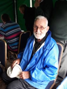
Roy Bartlam G0HDF (1951-2022) SK
An appreciation of Roy’s life by Chris Pettitt G0EYO and Peter Green G4LWF/G4MEB, after discussions with David Hillyer G0RQO (ex MEB), Emma Sedgewick and other friends.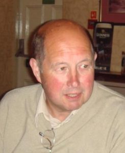
It was with great sadness that Wythall Radio Club heard of the passing of long time member Roy G0HDF in June 2022 at the age of 71 after a long illness.
Born in Birmingham, Roy was a single man and lived most of his life in Weoley Castle and worked at the MEB until he took early retirement. He was active in Wythall Radio Club, participating in club contests, helping setting up and manning the doors at their radio rallies, social events and was a regular at weekly club meetings.
Roy’s association with the club goes back to the late 1980’s when he and his friend Tony G1PKG (who he met at a morse class in the early 80’s) became regular visitors. Tony tragically lost his wife in 1988 and Roy became sort of “uncle” to Tony’s daughter Emma, who was only 9 at the time. In fact, when Roy became ill in 2021, and could no longer look after himself, it was Emma who took him into her home with her family and nursed him up until his passing.
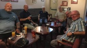
Photo below: At Wythall Radio Club August 2020: L-R: Kev 2E0NCO, Roy G0HDF, Les G0HOR, Mike G4VPD, Phil 2E0WTH and Pete M5DUO
 A non-smoker, Roy found out he was a diabetic when he was younger and so he became a bit of a fitness fanatic to keep himself healthy.
He loved swimming and riding his bike, so it was ironic that following an accident on his bike where he hurt his hip, that other things where found to be wrong. His breathing became difficult, he was thought to have angina and fell into a diabetic coma a couple of times. Eventually they discovered he had a secondary cancer but could not establish the primary cause.
Roy was well known for his cheerful nature and after retirement he indulged his love of travel and spent many holidays in Spain, Cyprus, Malta, Egypt where he had friends and relatives. All his friends and family knew him as a very patient man who never had a cross word for anyone. But he could have a wicked sense of humour.
Roy had other interests than amateur radio and foreign travel. He used to be a keen bowls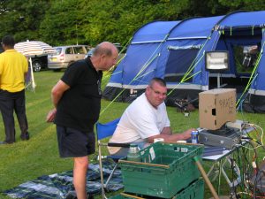 player, indoor in the winter and outdoors in the summer. He was also captain of his local team. Emma tells me that he was very keen on banger racing when he was younger.
Roy leaves an older sister Violet and her family who live in Banbury. He will be missed. RIP old friend.
(Prepared by Chris Pettitt G0EYO following discussion with Emma Sedgewick)
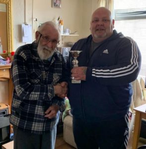
Photo right: Roy G0HDF and Callum M0MCX at Wythall Radio Club VHF NFD 2013
The MEB Years by Peter Green
I first met Roy around 1980/81 when the MEB Radio Club was formed at the MEB Headquarters at the top of Mucklow Hill, Halesowen. At that time Roy worked for MEB in Birmingham as an electrical fitter wiring three phase meters at customer’s premises. Roy was a member of the radio club until we were forced out of Mucklow Hill and the Sports Club closed in 1998.
It was Roy who suggested those of us left should move to Wythall Radio Club and join in their activities. Roy was always an active member of both radio clubs supporting, field days, special events and at Wythall the annual Rally.
During the 1990’s we would take a portable station up Walton Hill (Clent) for an evening in June with generator and hand rotated mast plus vhf beam aerial. Operation would be from 7:30 pm local time until sunset when a strip down and pack away took place before we lost the light, coming down the hill in semi darkness. Roy along with Rob Jackson carried the generator up the hill and back down later on. One notable night we were tracked by a police helicopter while walking down off Walton Hill with the portable aerial, radios, toolbox, torches and generator. Roy waved at them at one point and they moved on.
Roy was always involved in any maintenance, mainly aerials – both HF (G5RV) and VHF/UHF Beams at G4MEB. Roy’s interest in our club aerials allowed him to build his aerials at the home QTH as well as aerial switch boxes and a 150 watt 50 ohm dummy load in a large coffee tin good enough for HF use.
Roy retired from the MEB in 2002 and found more time to get involved with new interests such as stocks and shares, bowls – indoor, walking, riding a bike along the canals of Birmingham and swimming (at least twice a week for a mile each session). Regular Spanish holidays for weeks at a time plus Malta and Cyprus as other locations kept Roy fully occupied.
At that time Roy also became more active with Wythall Club projects either with or without his MEB colleagues. At Wythall Rally, Roy would attempt to be on site very early on both days and carryout whatever duties he was assigned.
I’m sure there is a lot regarding Wythall that I am not aware off. Roy always appeared everywhere in support of the WRC. He was a great character, a one off who got well known to many folk around the Birmingham area.
He will be missed by many as the cheerful guy who would pop up at any time and be welcomed.
Peter Green G4LWF/G4MEB
8 th July 2022
 and Play’ field day last Saturday.
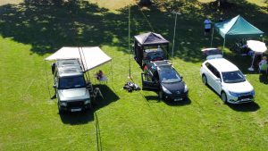
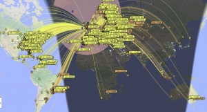
 We chose this Saturday to coincide with the IARU HF Contest so there would be lots of activity on SSB
 and CW, although we weren’t entering the contest and had lots of time to chat with stations on 2 meters FM and non-contest stations on HF.
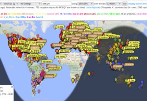
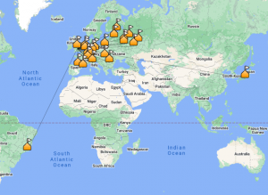
  Meanwhile, Ian M0LQY was busy on FT8 – especially on 20m and 17m – with DX highpoints working VP2EIH in Anquilla and Club member Chris G0EYO in nearby Redditch!
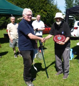


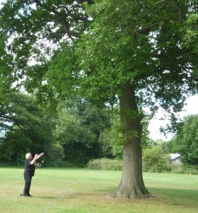
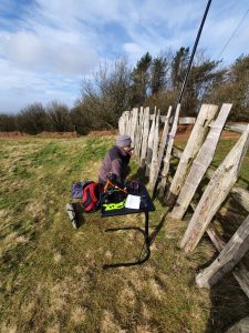
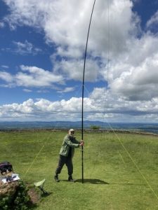 on a recent dxpedition to Bredon Hill – where we had 4 seasons in one day!
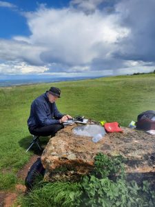 Trailing behind like a malnourished Sherpa, I possibly delayed the arrival time by half an hour but we were soon into the swing with Chris G0EYO responding first to my rare outing with the 2 meter Handie, followed by Don, G0NES: both good signals.
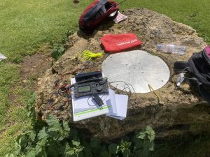 Big thanks to Chris for patiently guiding this SOTA novice through the experience: I’m off now to find some batteries for the KX3 and .. work on my fitness!
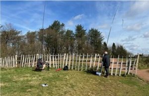
 Sadly, Jim 2E0BLP has announced that he is going to retire from serious club contest efforts.
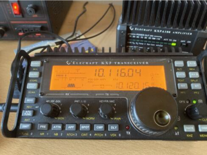 We have paused our Foundation and Intermediate Training Programme due to recent RSGB syllabus changes that require major updates to our training materials.
 ‘Having fun with RF!’ – was how Wythall Radio Club members spent last weekend.
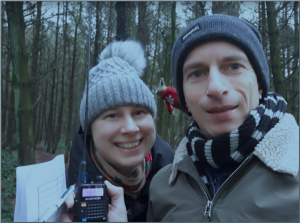
 Meantime, Clive M7OCB and Chris G3YHF had some fun out SOTA’ing to activate
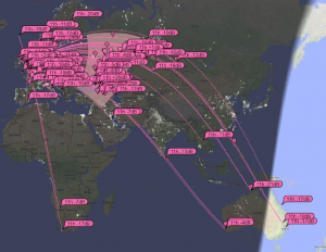
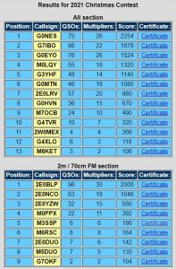
 Club’s Christmas Contest 2021!
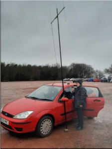 In our ‘Top Scoring Foundation Licencee’ section, Sylwia M3SSP came first in the 2 and 70 category and Clive M7OCB in the ‘all bands and modes’ section.