 A 3 week programme covering:
- How to get going with your Raspberry Pi
- Connecting to your network and other computers
- Compiling ham radio programmes from source code
Tuesday, March 10th, 17th, 24th 8 – 9.30pm,
Darts Room, Wythall House, Silver Street, Wythall B47 6LZ
with Ian Gilmore M0LQY
Free course, but please make a small donation towards room hire.
To reserve a place, e-mail us at: wythallradio@gmail.com
Most hams will have noticed that world of amateur radio is undergoing a transformation. The analogue nature of radio design is rapidly being swept aside and replaced by digital designs.
Recent models by radio manufacturers are all based upon Software Defined Radio Technology (SDR) Better sensitivity, selectivity and filtering can be provided by software than would have been previously possible. Even familiar meters displaying, power SWR, ALC etc. are created in software using TFT screens instead of older analogue meters.
 Additional information once fixed is now configurable according to operator preference. Electronics under software control is the new standard and there can be no going back.
A common trait amongst HAM’s is the desire to experiment finding new ways to improve the performance of our radios and whether this means designing and building circuits, constructing new antennas or finding innovative ways of controlling our radios is now possible using software. We routinely attach our radios to computers either to control, display information or to operate one of the many digital modes available to us.
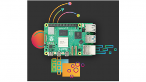
Although many of us routinely connect our radios to a PC or laptop running Microsoft Windows this is not the only option. The Raspberry Pi is a real alternative. This is a true mini-computer that has become a favourite amongst licence HAM’s.
This remarkable device now on its fifth generation has become a truly powerful computer and unlike the closed nature of expensive Microsoft products it utilises software freely available to all and actively encourages users to experiment.
Taking full advantage of opensource software, you can learn to program and develop controls to support your own projects. Many of you may already have discovered this marvel and want to extract maximum value from it. Alternatively, you maybe are thinking of giving it a try or just want to know more. Well, we can help!
 For those with an interest in learning how to get going with a Pi then this is your chance.
Wythall Radio Club is hosting a series of workshops beginning in March which will guide and advise members on buying, powering and connecting peripherals.
The workshops will guide you through the process of setting up a new installation and installing key Ham Radio programs. Hopefully, we will dispel many of the myths about complexity, the command windows or other unfounded rumours which are often heard.
Later sessions will progress into networking and connecting to other computers running windows or other Unix based systems such as Apple Mackintosh. Another issue we will cover is Unix permissions which often confuses new users.
We will look into compiling programs from source code which is something that is a very useful skill since some applications are only distributed as source code. Some of you may want to go on to write your own programs or just want to improve your skills or understanding.
 The Raspberry Pi is an ideal platform for Radio Hams to develop skills to further your knowledge of software-controlled electronics. Additionally, the Pi is excellent at performing more traditional computer tasks.
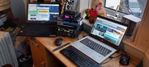
A Ham wanting a small computer for field days, running a local hotspot or controlling your radio then the Raspberry Pi is for you. The Pi is a real computer that can be used for all of the traditional tasks expected of a PC whether it is email, writing documents or keeping a spreadsheet.
Come and join us in March and begin your Raspberry Pi Journey. Who knows where it will lead you to.


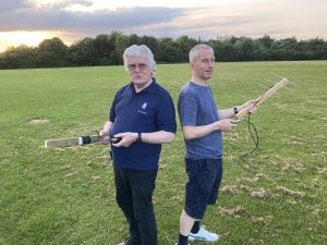
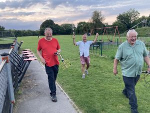
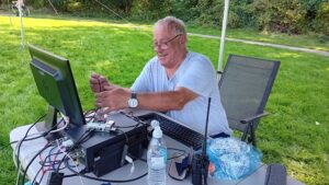 See Wythall Radio Club members operating via satellite and short wave radio at
 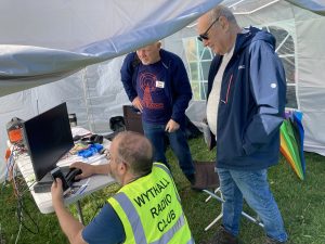 Visitors of all ages are welcome.
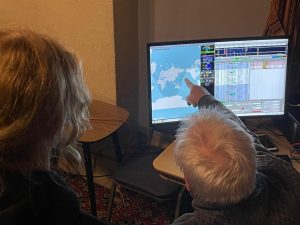
 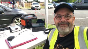 Neil G1TZC, Wythall Radio Club’s enthusiast for using the QO100 geostationary satellite, recently took a trip to Guernsey. Of course, he took his portable satellite station and the Club’s dish with him. Here’s his report on his dxpedition.
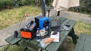 During the week there was time for three stints on the air under the GU call. 101 contacts were made in about three hours on air. Highlights included UAE, Iraq, Brazil and the Balearic Islands.
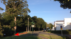 It was a little bit of a maze, but my ears were able to home in on the faint sound of HF in the distance. Following the sound, a person was eventually found. “Hi, I’m Keith – GU6EFB”.
 And chat afterwards in the bar of Wythall House.
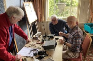
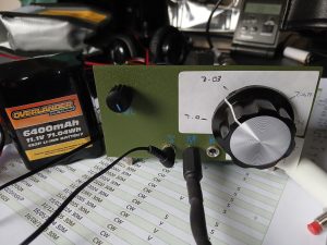 Just the job for a little refresher or first time soldering and coil winding – there will be expert helpers on hand to advise where necessary!
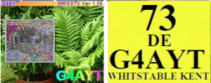
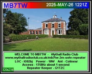 Things have been fairly quiet recently on MB7TW – Wythall Radio Club’s 2 meter SSTV (slow scan TV) repeater.
 You can see behind the scenes of a solo dxpedition at Wythall Radio Club next Tuesday 7th April at 8pm.
 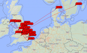 High pressure and early mist – maybe there will be some enhancement on 50MHz and 144MHz today?
 Lots of PSKreporter spots on 6m, with +1db from Sweden and -9db from Denmark – nice!