Wythall Radio Club’s Christmas Contest is approaching fast!! If you only have a basic 2 meter antenna or just a handheld, or you want to get out portable, here’s an easy-to-build 2 meter antenna to boost your signal – from Neil G1TZC.
There is a link to a pdf version at the end.
Many years ago I read an article somewhere about the Slim Jim portable antenna. It might have been in Practical Wireless, but was a very long time ago.
Thanks to the late Fred Judd (G2BCX) we have this great little antenna available to us.
I decided that now there is an antenna analyser in the workshop (see previuous post on the nanoVNA), it was time to revisit this old friend. After a bit of digging around the internet, various measurements were found and duly scribbled on a sheet of A4 paper.
From my memories of the one that I built many years ago was made from choc-blok (electrical connector – 15A) and coat hangers.
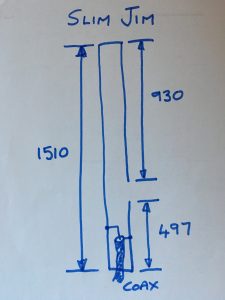
Initial sketch
We had also better think about some sort of base as well, as this version will be a table top version.
Ingredients
4 wire coat hangers (10 for £1 from Poundland last time I looked)
3 choc blok electrical connectors (15A)
1 length 50ohm coax with suitable connector for your radio
1 bamboo kebab skewer (yes really)
Material to make a base and fixing screws.
Tools
Wire cutters
Pliers
Craft knife
Terminal screwdriver (small flathead)
Tape measure
Soldering iron (optional)
How we make it
Let’s start with the good bit. Let me begin by apologising for the quality of photographs – they were done on the fly without a tripod or lighting and on a phone.
Take the choc blok. Cut this so that there are three terminals per strip. The ones used here were 6 way 15A, but you may be using something different.
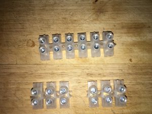
Complete and cut connector block
Cut the hook section off the four wire coat hangers and straighten. Remember if there is any coating this either needs removing or scraping to bare metal for joining areas.
You should now have four lengths of wire. To absolutely maximise the available metal cut off two of the hooks from the twisted section and straighten. These will make the two ends of the antenna. Exact measurements for these can’t be given because your choc blok will vary in size.
Fold short lengths of wire with a pair of pliers
Loosen the screws and insert the wire as shown above. Cutting these slightly long allows you to change the length of the antenna during testing. Always handy to have a little bit of give, just in case.
Now take two of the long lengths of wire and cut them to 930mmin length. In a perfect world these will slot through the choc block a bit like a trombone. Take another two three way connectors and remove the metal terminal from both. Do not throw these connectors or screws away as we will use them later.
Slide one of the three way connectors about half way along the two lengths of wire and tighten the screws. This is simply used as a spacer. Now use the other connector at the open end of the two wires and tighten slightly. Again, we are going to leave the option to trombone the metal a little if needed.
Take one of the remaining lengths of straight wire and cut it to 580mm.
Now cut the last length of wire to a length of 497mm (500mm will be close enough).
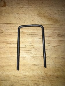
Find the other end section that was made earlier and insert the two wires to make an unbalanced U shape.
More hunting. Find the two metal inserts that you set aside earlier. Here we have one of two choices. If you don’t have a soldering iron to hand then simply slide one of the metal inserts on to each of the legs of the unbalanced U.
If you have a soldering iron, strip the end of the coax cable ready for soldering.
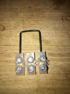
Solder the inserts as shown. Note one screw hole on each is uncovered.
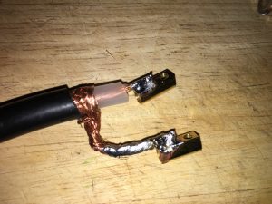
Once the ends are soldered and cooled slip them on to the unbalanced U section. The inner is connected to the longer leg and the braid to the shorter side. Pinch tighten these close to the base of the U. This will allow you to adjust the feed point. In the workshop this was set at about 50mm to start.
Now slide a 3 way as a spacer on the unbalanced U section and tighten. Using the final 3 way slide it in to place so that the short section is just fed through the connector. Tighten this connector on both sides.
Connect the long side to the original U section and tighten. In the workshop version the kebab skewer was used in the middle of two of the connectors so that it strengthens the gap section.
Effectively, the antenna is now complete and ready for use. You could now tie a piece of string to the top and hang it somewhere (or tie spare bit of bent metal to the end and hang it over something).
Alternatively, the antenna can be bent through 90 degrees to make a table top version. Let’s come back to that later.
Testing
Connect the antenna to your analyser – BUT DON’T DON’T WORRY IF YOU DON’T HAVE ONE!
Testing can also be done by connnecting your 2 meter transceiver, low power setting, with your VSWR meter inline.
(OR if you only have a handheld, and no VSWR meter, then try listening on the 2 meter band. If you can hear signals (especially if they are stronger than on a rubber duck antenna), chances are it will work fine.)
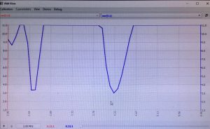
Adjust the feed point as required to give the lowest reading you can. Once you have reached the lowest point you can also adjust the overall length of the antenna from the various connectors. This may increase or decrease the VSWR readings. This is a bit experimental but that’s what the hobby is about. The analyser plot below gives 1.5 or better right across the band.
The antenna should also work on 70cms – two for the price of one!
Analyser plot for the coat hanger slim jim
Optional Base
If the option of base is required here is an option that was put together in the workshop. A length of 30mm wide pine was left over from lining the workshop roof so this was used for my base.
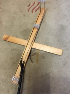
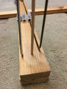
Foldable wooden base Close up of skewer
Cut the base slightly longer than the bent section of antenna. Glue two 30mm square blocks on the underside, one at each end. Measure another length to be fitted in the gap in the underside. Make this section 20mm shorter than the gap to allow for rotation to make a foot. Place this strip in the middle of the gap and screw so that strip can be rotated. You might want to drill a pilot hole to allow free turning. If you use a long enough skewer you can use it to stabilise the upright. Drill a hole small enough for a tight fit and push the skewer in to place.
I hope these instructions worked for you and you enjoyed it as a little project.
You can print off these instructions as a pdf by clicking here.
Neil – G1TZC


 Latest News from Training Co-ordinator, Chris G0EYO is that the next on-line Intermediate Course is planned for a 28th June 2021 start and will last for 10 weeks and the next on-line Foundation course is expected to start in August.
  2021.
2021. This will take place over an 8 week period with two lessons per week in the comfort of your own home and in a time of your choosing. We will deliver all the course material you need to complete the course but you will have to purchase the RSGB book “The Foundation Licence Manual” from the RSGB shop
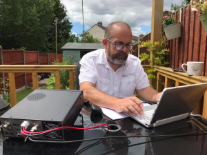 Network Analyser….
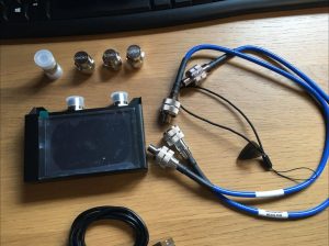 Recently I purchased a four inch screen version of the NanoVNA. I decided to pay a little more for a premium version.
 If you have a little bit of spare cash and you want a handy test tool this is great. It allows you to check that antenna from the end of the coax.
 STOP PRESS – THE INTERMEDIATE COURSE IS NOW FULL. FOUNDATION COURSE STILL AVAILABLE.
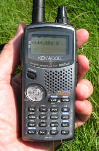 There is no charge for doing these courses and we do provide individual tuition via quizzes etc. Please note that there are specific IT requirements which have to be met for the online examinations.
 Our courses are done through a Virtual Learning Experience called Edmodo and comprise a number of video lessons (via YouTube) plus lesson notes and lesson quizzes and other supporting information.
 You also do not have to be a member of
  student do join us.

 An added high point was a visit to the fridge that Kev 2E0NCO keeps stocked next to his operating position!